Home > Tech Tools > Technical Papers > The Affects of Capacitor Geometries
To understand the effects of geometry on finished capacitor functions it is first important to understand the section geometry (basic winding unencapsulated).
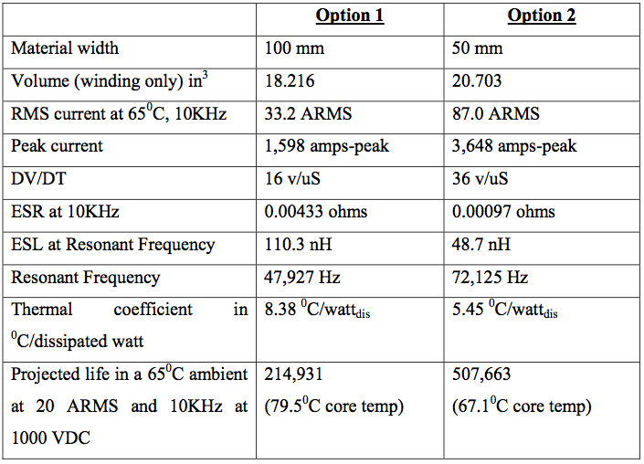
In general, the shorter the section is the better it will function. The ideal capacitor would generally have the apparent diameter to length ratio of a hockey puck. The more end area there is, the more peak current the unit can handle. In addition, since the bulk of the heat generated in the center of the capacitor moves axially along the foil or metallization on the film, the shorter the distance from the geometric center to the endspray the more heat that can be dissipated. Combine the short thermal path with large end surface area and the RMS power of the unit is very high. Consider the following comparison of two different windings for the same capacitor value. Both windings are based on the same clear margin width, mandrel diameter, film thickness and metallization deposit thickness with the only variation being material width.

It quickly becomes apparent that half the material width dramatically increases the performance of the capacitor winding. Notice that there is a 13.65% increase in volume. This is the affect of a fixed clear margin width and offset. The active area required to yield 100uF is the same for the same material thickness.
There is also a reliability aspect to consider. When the same power is applied to both units, the shorter unit will exhibit less heating at the capacitor center. Therefore, since the internal core temperature of the shorter winding is cooler the capacitor life is extended. The capacitors are produced from organic materials, which generally follow the 100 C rule of life where half the temperature results in twice the life.
J. Bond
Engineering Manager
Electronic Concepts Inc.
January 2005 – Revision A


