Home > Tech Tools > Application Notes > AC Filter Capacitors for PWM Inverter

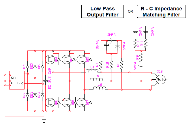
The overall variable frequency drive (VFD) system relies on capacitors to control an AC induction motor properly. The VFD system includes an input sine filter, AC/DC converter, DC link, DC/AC inverter, and AC inverter output filer.
Within the VFD are DC bus capacitors, located between the output of the AC/DC converter and the input to the DC/AC inverter. These high-energy capacitors store energy, smooth rectifier ripple currents, and provide “ride – through capability” required to lower the total harmonic distortion (THD) from the drive’s rectifier.
At the VFD’s output, transient voltage spikes occur from fast-switching transistors and long cable runs to the motor. AC filter capacitors on the inverter output serve to absorb transients and filter the harmonic current spectrums. Broadband harmonic current spectrums result from the DC chopping for pulse width modulation (PWM) output to the motor. These harmonic currents (usually the odd 3rd to 11th harmonics are the highest currents) are superimposed on the carrier or fundamental wave at 50/60Hz.
Electronic Concepts offers several UL Recognized AC filter capacitors specifically designed for inverter outputs including:
- Electronic Concepts’ 5MPA line of high current, broad RMS spectrum, AC capacitors. The unique rugged terminations and robust design of the 5MPA capacitors are particularly suited for PWM outputs, and handle current spectrums from both line frequency and superimposed harmonic ripple on the carrier wave. Multiple internal connection joints provide excellent current distribution, and the flat copper terminations offer wide frequency response with low electrical and thermal impedance.
- Electronic Concepts’ 3MPA line of plastic housed AC capacitors is an extension of the 5MPA technology into larger capacitor enclosures with mechanical mountings integrated into package. The design of these capacitors provides the highest RMS and peak current capabilities. Internal connections of wide flat copper with redundant weld joints, provide excellent performance and reliability.
- Electronic Concepts’ 3MPS line is exactly the same as the 3MPA line with the added safety of a patented resettable thermal cutout (TCO) located at the capacitor hotspot. This allows the user a parallel feedback circuit, electrically isolated from the capacitor, but thermally integrated into the assembly. In the event the capacitor internal temperature begins to rise beyond 85C, the thermal cutout opens. The cutouts can be used with a relay, contactor, or other device to set in motion corrective or diagnostic protocols before catastrophic failure occurs. After the capacitors cool, the TCO resets, and the capacitors may be re-energized for operation. Filters consisting of multiple capacitors can series connect the TCOs from one to another and thus minimize the input to the system to a single pair of signal wires.
- Electronic Concepts 5MPF line of aluminum enclosed AC capacitors employing a series thermal fuse. The thermal fuse in series with the capacitor and provides a permanent disconnect if the internal capacitor temperature at the hotspot exceeds 90C. This safety is automatically fired as a factor of internal temperature and it is not resettable, however it does not require system actions to function.
Good engineering practices noteworthy at the system design level include:
- Always use separate mechanical means of mounting the capacitor. The electrical terminals should never serve as the sole mechanical supports. Using electrical terminations as mechanical mountings could create internal damage, which over time may lead to premature and possibly catastrophic failure.
- Allow stress relief in connections to allow for thermal expansions and contractions across the temperature range. Mounting devices rigidly between solid bus bars, which are also rigidly tied to the system, does not allow the capacitors to move with expansion and contraction. This may cause internal termination damage, which over time may lead to premature and possibly catastrophic failure.
- Be aware of the location of the capacitors to heat sources such as reactors, inductors, transformers, and other heat producers. Premature or catastrophic failure can occur from external heat sources overheating the capacitor in operation when combined with hotspot heat rise created from normal capacitor losses.
For more information on this and other ECI capacitor products click on the link below:
www.ecicaps.com
Original: J. Bond – 2002
Revision A: J. Bond – Dec. 22, 2014


